|
| Author |
Message |
mroy0404
Member
|
# Posted: 1 Jun 2012 07:32pm
Reply
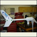
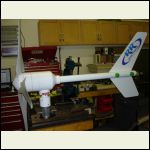
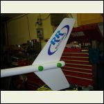
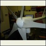
Here are afew pic's of the CNC machined wind turbine I have been working on this past spring. The prototype has worked so well, I made 4 more units!! The 4 newer units have been powder coated white and I used all 304 stainless steel fastners to hold them all together.
Tell me what you think of the design.
Here is a link to my photobucket page.
http://s41.photobucket.com/albums/e288/mroy0404/Wind%20Turbine/
DSC06148.JPG
| 
DSC06149.JPG
| 
DSC06152.JPG
| 
DSC06154.JPG
|
|
|
Martian
Member
|
# Posted: 1 Jun 2012 08:19pm
Reply
Your design looks nice. Do you have any specific operating data, and are you going to sell them? How much?
Tom
|
|
mroy0404
Member
|
# Posted: 1 Jun 2012 08:33pm
Reply
Thank you, my wife and I have been working on this project in our shop this past 4 months. We have a prototype up and running for the past 2 months. We have seen power output of 18.6 volts and 40 amps so far. We have had alot of interest from friends, so we machined up 4 more units. They have all been CNC Machined from solid 7" Dia. 6061-T6 Aluminum on a 6 axis CNC Lathe and use 304 stainless steel fastners to hold them all together. They also have a 50 amp slip ring so wires will never tangle up. There are 6 sealed over sized ball bearings supporting all moving parts. We may have went way over kill in the design, but this is built to last a lifetime. If we get enough interest, we will sell these units.
|
|
analogmanca
Member
|
# Posted: 1 Jun 2012 11:02pm - Edited by: analogmanca
Reply
mroy0404
Quoting: mroy0404 Tell me what you think of the design.
Well you have not said anything relevant relating to the design that can be commented on. A pretty picture means squat. Claiming that what appears be to be roughly a 4 foot diameter rotor ( I guess 5 foot at most) against a claimed output of 1000 watts is going to place you outside the bounds of the possible. Sticking to that claim will find you on the pointy end of a stick.
I understand you have just built this, and its your baby, you are happy with it as you should be, as it takes skill, and effort to build something that works, but you need to familiarize yourself with the betz limit (59%) and what I think is called the cp (efficience of power conversion 35% )
With a 5 foot diameter rotor in a 20 mile per hour wind the maximum power is 800 watts, but only perfect blades will capture the wind up to the betz limit of 59% .
So that gives you 472 watts that a perfectly effecient set of blades can capture on a 5 foot rotor at a 20 mile perhr wind speed. Now thanks to winding losses,magnet drag losses, bearing losses, conversion losses, and others we apply a cp of 35%, on the 800, we get 280 watts theoretically possible with perfect blades, and a very,very well buit alternator. You do not have anything near perfect for blade design, and I suspect a less than perfect alternator design. So to be kind, and I think generous lets use 26 for our cp, that will net 208 watts. So by my estimation you have at best what I would call a roughly 200 watt mill.
I do math on my fingers, and claim no degrees in anything, these values can be pulled off standard enginering charts.
If you wish to have a honest evaluation of your product, head on over to the otherpower board, or anotherpower board , and run your project by anyone there, though I suggest Chriss Olsen as he is a enginer who will give you a very acurate evaluation of its output, and I suspect he will be less generious than I am.
Or as I see you are in Canada just ship me one, I have 40 foot tip up tower to put it on, and can log real data off it, and even compare the output to others.
PS. I would have been happy to just smile, and wave, but as you are talking of selling these a acurate assessment is needed.
|
|
analogmanca
Member
|
# Posted: 2 Jun 2012 12:55am - Edited by: analogmanca
Reply
I mean to add that in no way do I think you mean to misslead. Only the enthusasum of building something has gotten ahead of the testing. I have been there as years ago I have build motor conversions with neo mags, and tested them by driving them in a lathe, into dummy loads, and getting great data that fell on its face when flown in the wind.
Also, I see no furling mechanism or braking function, how are you limiting rpms? What load are you using for your tests? I have found the best load to use is a diode stack as its a little bit dynamic like a battery bank can be, but can handle hundreds of amps all day long while testing in the roughest wind conditions. The one pictured is set up for 12 volts, and can handle 300 amps all day long. A cover goes on the front, and a small 33 watt 12 to 24vdc muffin fan blows up from the bottom to keep everything cool.
Now that I see more of your pics even more questions come to mind, it looks like you have built a 3 phase stator, and I suspect your rotor will be permanent magnet. If thats the case and as you say its ( the stator block) machined from aluminium then in my experience passing a magnetic field through aluminium generates back emf that may be opposing the direction of rotation, and generating unwanted heat in those stator winding, also as you have cnc capability why not skew the winding? ( for reducing start up cogging)or did you try, and found no benifit with a alumimium stator block? So many questions, you really need to run this by those guys at the sites I gave you, they eat this design stuff up, and the advice, and experience of some very sharp minds is free. ( I just now see you did, I will follow with interest)
|
|
|

