| << . 1 . 2 . 3 . 4 . 5 . 6 . 7 . 8 . 9 . 10 ... 12 . 13 . >> |
| Author |
Message |
ICC
Member
|
# Posted: 30 Dec 2020 02:45pm
Reply
Quoting: paulz Right now the SCC says battery is at 13.7 but only showing 13.3 at the battery.
So, the meter on the SCC indicates 13.7 to the battery and a separate, different voltmeter indicates 13.3 when the battery terminals are probed?
Is it possible to take a voltage reading at the output terminals on the SCC with that same meter that is being probed at the battery terminals? Just to see if it reads 13.3 or 13.7. The reading should be the same when taken with the same meter. IF the wiring was bad enough to cause a problem the voltage reading would be expected to be lower at the battery than at the output terminals on the SCC.
It would appear that one of the readings is incorrect. Not knowing what meter you use I make no guesses as to which is correct as the SCC is not exactly what I would call top end.
Do you have another meter? Somebody else with a meter you could check readings with? You don't need an expensive Fluke (although I love mine) but some of the cheapy meters are not as accurate as I would want.
|
|
ICC
Member
|
# Posted: 30 Dec 2020 02:49pm - Edited by: ICC
Reply
If you look for a better meter look at getting a clamp meter. They do everything a standard multimeter can do plus they can measure actual current flowing through a wire. (needs to be able to fit the metering jaws over a single conductor, not a pair together in a cord.
Easy to measure current flow from panels as well as out of the SCC. There are decent ones in the $60 range
|
|
gcrank1
Member
|
# Posted: 30 Dec 2020 03:15pm - Edited by: gcrank1
Reply
With the bat at 13.3-13.7 I would expect to see that low 4 amps, or less, on my mppt display after an afternoon charging and a night of not, no load.
On your initial hookup I would have expected more than that 2amps to 50% soc bat(s). You could have too much resistance in the connections and/or drop in the wiring for gauge or distance, and clip-on clamps are poor.
Still, the bat topped up to an apparent well charged 13.4+, will it hold there? Or what does it settle out to?
Fwiw, and iirc, someone told me to expect like 70% of the 'rated max amps', in your case that 8a would be 5.6a (or multiples thereof depending up your setup), this due to the losses in system by the time it is getting delivered to the battery (lines, connections, mppt, the internal step down transformer to 12v from 24, etc).
|
|
paulz
Member
|
# Posted: 30 Dec 2020 06:49pm
Reply
Quoting: ICC So, the meter on the SCC indicates 13.7 to the battery and a separate, different voltmeter indicates 13.3 when the battery terminals are probed?
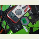
What a mess. Fist of all, my DVM doesn't match the fancy meter gizmo I bought to monitor the batteries mounted in the truck. The DVM does match two other volt meters on my battery bench. Harumph..
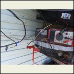
The SCC voltage matches what's at the SCC terminals via the DVM, but I'm still losing about .2-3 volts by the time it reaches the battery. Like I said, I have a 25ft. standard extension cord going from the SCC to the truck, and a couple of 110v plugs at either end, so maybe that is the problem.
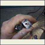
I also found that by wigging the MC4 connector connecting the two panels in series changed the panel voltage on the SCC. Pulled it apart and found corrosion. These panels have been sitting unconnected since I got them, back at page 2 of this thread whenever that was, or it may have occurred while in use at the old location. I was able to squeeze the male connector and get a tight fit and stable voltage, which has been around 60 all day at the SCC.
That has me wondering about all the connectors in use at the cabin. One of those clamp on meters would be a great idea if I can use it to test connections like that, just by moving it around. Think so?
mc4.jpg
| 
meter.jpg
| 
meterr.jpg
|  |
|
|
gcrank1
Member
|
# Posted: 30 Dec 2020 08:00pm
Reply
Now that you have found corrosion in one con they are all suspect (and maybe poor-bad performance was why the po got rid of them?). I recommend pulling them all apart to inspect closely. You can get a pack of new MC4's and a crimp tool, cut all wires back and re-do. Or you can eliminate maybe quite a few by wiring them direct; ie, no MC4. Cut back wires, strip to clean wires, anti-corrosion grease, crimp on butt con's and shrink tubing.
Standard extension cord? No such thing, they are all over the place in wire gauge, quality of insulation, place of manufacture..... Use the online line loss calc's to figure distance for load and upsize by one ga. Contractor's cords are likely best in 'std', after that the much heavier RV cords. The 30amp 120 RV cords I think are 10ga. multi-strand compared to the Contractor type for 20a load with 12ga. Then there are the 50a RV cords.
Ime fat, fine,multi-strand wire is best array to cc and cc to bats. Im running 8ga. on the 24vdc panels (what they came with) to 12' of 10ga (should be 8, but this is what I had) to cc. From cc to 12v bat's is 10' of salvaged Decent jumper cable wire (Not the coarse multi-strand cheapie jumpers). Im close to maxed out for those distances. The 90' to my cabin from the powerhouse would be Huge money for dc so I invert to 110vac at the powerhouse. 110vac runs distance far easier than lower voltage dc.
|
|
paulz
Member
|
# Posted: 2 Jan 2021 06:04pm
Reply
Thinking about upgrading the charge controller in my cabin, from a Renogy Rover to a Victron Smart Solar I can get a good deal on. Both MPPT of course.
Most everyone says the Victron is top of the line, Renogy the bottom. Could I expect better performance, or reliability, or what?
|
|
gcrank1
Member
|
# Posted: 2 Jan 2021 06:13pm
Reply
I have read that Renogy used to be 'better' than now, I dont know and maybe yours is one of their better ones?
And Victron seems to be always well regarded, older and new.
Were I buying new stuff Id want to go Victron, dont know if I could afford it.
But you always seem to find the deals.....
Ive been thinking about picking up another cc so I can have 2 dedicated arrays.
How many amp is your Ren?
What is the max gauge wires that fit into it?
|
|
paulz
Member
|
# Posted: 2 Jan 2021 07:30pm
Reply
My Renogy is 30 amp, I think 6 is the max wire. It seems to work fine, only reason I'd consider the Victron is if it did a better job of charging, pound for pound.
|
|
|
FishHog
Member
|
# Posted: 2 Jan 2021 07:45pm
Reply
Reliability will probably be better with the Victron but performance wise I suspect you won’t be able to notice a difference.
I’m usually a believer in “don’t fix what ain’t brokeâ€
If I was buying outright I’d get the victron but not sure I’d bother upgrading just to change brand if yours is working
|
|
scott100
Member
|
# Posted: 2 Jan 2021 08:16pm - Edited by: scott100
Reply
One other nice feature with the Victron smart controllers is the interface you get with their app. Among other things, you get a nice history page like the one below. It looks like Renogy may have something similar if you buy their bluetooth adaptor.
One other nice thing with the Victrons is that they are completely programmable, so you can set custom settings for absorption, float and equalization voltages and other parameters based on what the battery manufacturer recommends.
|
|
ICC
Member
|
# Posted: 2 Jan 2021 09:22pm - Edited by: ICC
Reply
Victron wins out over Renogy every day. But if you are going to switch have a hard look at what capacity you should buy; bigger capacity ight be better, depending on many factors. I do like the Victrons programmability and app.... bluetooth, usb and wifi
It may not really be worth changing unless you have a technical reason to do so, or just want some feature or ability that Victron offers.
While on the subject of a possible upgrade, I prefer to use the same brand equipment for the charge controller and the inverter as the apps can tie the whole system info together in one place. If not with an android, apple or PC app, then in a wall mounted accessory panel. Or both.
|
|
paulz
Member
|
# Posted: 3 Jan 2021 02:51pm
Reply
Quoting: scott100 Among other things, you get a nice history page like the one below.
That is neat. The Renogy is user programmable for battery specs as well, though I have just selected the pre-programmed FLA, Gel, Li etc. options.
The Victron for sale locally is a 100v 50a, my Renogy is 100/30. Not sure I'll ever even see 30a, but possible this summer I guess. Do any of you guys see charges that high?
The Victron doesn't appear to have a display like the Renogy, must have to use a separate thing.
Renogys are about half the price, new, of Victrons, from what I can see.
|
|
gcrank1
Member
|
# Posted: 3 Jan 2021 03:23pm
Reply
I have a Blue Sky Solar Boost 50 c/w display. Ive never seen close to a '50'.
If Ive got it right, the rating on the cc is the max input from the array, not supposed to be its output?
Ie, ya add up the v and a the right way from parallel or series wired input to the cc , in your current Renogy case, a max 100v (4 x 21.5v panels = 86v, 5 x 21.5v would be too much at 107.5) and calc the amps from that number of panels to not exceed 30 you would be within spec?
You can juggle the series and/or parallel to keep your array(s) within spec and maximize your cc capacity.
Then you watch what the readouts actually amount to and wonder why it doesnt do what you thought it would.....well, that what happens with me anyway 
|
|
ICC
Member
|
# Posted: 3 Jan 2021 04:22pm - Edited by: ICC
Reply
Quoting: gcrank1 If Ive got it right, the rating on the cc is the max input from the array, not supposed to be its output?
The industry norm is that the amperage rating on a charge controller is the maximum amperage the CC can put out and into the battery bank.
The maximum input is rated in panel watts and that varies with the battery voltage. Higher battery voltage = higher maximum input watts.
The CC will also have a maximum input operating voltage. 140 to 150 volts is common. There are 200, 250, even 600 volt maximum units.
Schneider Conext 60-150 dtasheet link below.... the 60 is max amps output although it runs cooler if that is not run at that rate for long. The 150 in the system max volts. The table in the PDF lists max watts at 5250. IIRC the max amps output is less if one uses a 60 volt battery.
I have seen the amps output pegged.
|
|
gcrank1
Member
|
# Posted: 3 Jan 2021 04:52pm
Reply
"Higher battery voltage = higher maximum input watts".
But....watts is watts, it is the relationship of the voltage and amps that changes not the max watts.
|
|
ICC
Member
|
# Posted: 3 Jan 2021 05:50pm - Edited by: ICC
Reply
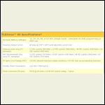
Typical example data sheet; note the PV array wattage limits go up with the battery voltage (... Take the rated output amps maximum x the battery bank voltage and the watts go up, meaning more watts input allowed.)
outback flexmax60 spec sheet screenshot
|  |  |  |
|
|
scott100
Member
|
# Posted: 3 Jan 2021 09:27pm
Reply
It's all about the current. Same max input current in all the examples of that spec sheet.
|
|
paulz
Member
|
# Posted: 9 Jan 2021 09:22am
Reply
I've been wanting to build a porch overhang for several years, just never could find the time, or what I would roof it with. Yesterday I solved the second problem, so found time for the first. Still need to button it up and wire it. This will be the 4th 3 panel string.
I put an offer in on the 50 amp Victron, just in case..
|
|
gcrank1
Member
|
# Posted: 9 Jan 2021 10:23am
Reply
Isnt the shadowing of the array corners at the roof eve going to compromise their output?
|
|
paulz
Member
|
# Posted: 9 Jan 2021 10:37am - Edited by: paulz
Reply
Sure, just like the trees and other shadowing on all my panels. Unfortunately there is a window up there. They are right at the top, and underneath is too low.
|
|
paulz
Member
|
# Posted: 25 Jan 2021 10:26am
Reply
So I got to thinking.. if, and once, your solar tops up your batteries while you are away, and you have no load, the rest of the energy potential is wasted right? Is it beyond imagination that the this could power a heating element, just enough to keep above the dew point for condensation control, in a small cabin?
|
|
gcrank1
Member
|
# Posted: 25 Jan 2021 10:35am
Reply
Would think so; isnt that is what is called a 'dump load'?
Maybe too a heating element with a simple thermal control to keep a battery box warm (like for a LFP bat)?
|
|
paulz
Member
|
# Posted: 25 Jan 2021 10:49am
Reply
Hmm, well now I recall someone saying the excess is already dumped by the SCC, that's why it has fins and clearances. Unless it also 'turns off' the excess some other way.
|
|
ICC
Member
|
# Posted: 25 Jan 2021 12:03pm
Reply
Quoting: paulz Hmm, well now I recall someone saying the excess is already dumped by the SCC, that's why it has fins and clearances. Unless it also 'turns off' the excess some other way.
The cooling fins are there to keep things cool when the MPPT CC is working. When the MPPT CC is taking in a higher voltage than the batteries there is heat generated as it does its power magic to make all incoming go into the batteries at a different voltage. Nothing is perfectly efficient and the loss goes out as heat.
When the batteries get fuller and fuller less energy is needed and the MPPT CC just stops accepting power from the PV array. No heat, no waste of what has been produced. A PV panel sitting there in the sun is ready to produce power but it doesn't have to actually go anywhere. A wind turbine is very different. A wind turbine will be damaged, maybe destroyed, if it runs without a CC that has a dump load and the batteries are full. As well as a dump load the horizontal axis turbines need a speed regulator, a brake or a mechanism that turns it out of the wind to keep the speed of the blades down to a safe speed.
A CC cannot be setup to operate as both a solar charge controller and a turbine generator at the same time. It is one or the other. And not all CC can do wind if they were designed for solar.
It gets complicated if you try to make use of the solar power that could be made if the batteries were not full. I have looked into it but gave up the idea. One of the ways to use excess solar ability is to use it for pumping water with pumps that are designed to be used with the varying voltage s that an array will be producing.
|
|
paulz
Member
|
# Posted: 25 Jan 2021 04:05pm
Reply
Quoting: ICC It gets complicated if you try to make use of the solar power that could be made if the batteries were not full.
You mean the extra after the batteries are full? That's what I was thinking. But sounds like it's not possible. Another alternative might be to power a heating coil off the batteries when they reach a certain voltage, and turn off when under. How 'bout that?
|
|
ICC
Member
|
# Posted: 25 Jan 2021 05:23pm
Reply
Sure. All you need is a control system and the switching system. Before figuring that out calculate how much energy will be available to harvest for these other uses and how beneficial will it be. When I looked into this idea I came to the conclusion it was not worth the effort and expense. YMMV.
|
|
Just
Member
|
# Posted: 27 Jan 2021 05:33pm
Reply
Added 1000 watts to old solar system to help on dark winter days . Got 4 used panels for 380$ canadian . Now have 2000 watts 73 volts into my 48 v mppt . Controller. Shut down tonight 5 pm .
|
|
Just
Member
|
# Posted: 27 Jan 2021 05:36pm
Reply
Bigger better
|
|
paulz
Member
|
# Posted: 27 Jan 2021 08:41pm
Reply
Nice. My two overpaneled systems are doing great even with no sun. Was out there today after a big storm, batteries fully charged. I don't know what the improvement factor is on rain washed panels but seem to work better.
|
|
paulz
Member
|
# Posted: 19 Feb 2021 08:35am - Edited by: paulz
Reply
Hit a bit of a solar milestone this week at the cabin. Ran entirely on the solar bank for 2 days and nights, instead of my home charged batteries. They had drained from an indicated 13.6v when I got there to 13.1 when I left but it still felt good to be self sufficient.
Here's something I'm curious about: I had been using only one of my Valence 140ah LFPs on the solar for testing. It showed around a 2 amp charge most of the day. Last week I put another Valence in parallel (I have one more I'm keeping home charged for backup), as that's what I have been using before running on the solar. Now the CC is showing about double the charging amps 4-5. Is that because of less internal resistance with two batteries? The sun situation really hasn't changed much, at least not that much.
With the 4-5 amp charge they should be good to go again when I return this weekend.
|
|
| << . 1 . 2 . 3 . 4 . 5 . 6 . 7 . 8 . 9 . 10 ... 12 . 13 . >> |

