|
| Author |
Message |
bronco_ed
Member
|
# Posted: 25 Sep 2017 09:06pm - Edited by: bronco_ed
Reply
I have for the most part mimicked the solar set up that Ontario Lake side has on his video. (Creeky's solar kit) However I would like to understand how the components all work together. In looking at the fuses for the inverter in the set up I am trying to understand how the 300 amp fuses were chosen. (That is all I have seen in the video)
The Victron inverter comes with 10 awg wire, in his setup it appears to be connected to the bus bar with the 300 amp fuse between the busbar and inverter.
I have read a few different sites on calculating fuse size I do not understand how such a large amperage fuse can be used?
I was thinking that you would want to protect the wire then no damage can be done to either the wire or component.
Can someone help me understand the process in fuse selection?
I am still confused on these charts ;)
**I just removed my thoughts on the charts** possibly due to voltage?
Thank you!
|
|
ICC
Member
|
# Posted: 25 Sep 2017 10:08pm
Reply
Fuses protect wire. The fuse should only allow up to what any wire in the circuit can safely handle.
If the inverter maximum input current is 100 amps the fuse to protect that wiring should only be a little larger than that.
Add all the circuit maximums and size the master fuse for the total current if everything was on at the same time, keeping in mind the fuses protect wires. So a 10 gauge wire should never have a fuse larger than 30 amps to protect that circuit.
Ideally the master fuse, closest to the battery, would be a type T, very fast acting.
|
|
razmichael
Member
|
# Posted: 26 Sep 2017 05:50am - Edited by: razmichael
Reply
Can I ask what capacity the inverter is (and DC voltage)? #10 cable on th DC Side seems very small. Looking at a 750w model Victron manual they suggest #8 at 48 volts and #4 at 12v input. I have often seen inverters sold as kits with wires that are seriously under sized even based on the recommended size in the manual. #4 or larger cables get very expensive! Have you checked the inverter manual? Lots of other general sites will provide a recommended size based on the max output of an inverter.
Edit: here is the recommended cables for my 12v Xantrex hf1800
Freedom HF 1800 Less than 5 feet (1.5 m) No. 2/0 AWG with 250 amp fuse
|
|
sparky30_06
Member
|
# Posted: 26 Sep 2017 12:14pm
Reply
Quoting: ICC So a 10 gauge wire should never have a fuse larger than 30 amps to protect that circuit.
when choosing a fuse size to protect wire several factors go into place. Temp rating of wire and connection points, insulation, is it in free are or in a duct of some type, and how many current carrying conductors are with it.
The general rule of thumb that will keep you from making toaster elements is a #10 wire should be protected by a 30 amp fuse. Anything large than 30 amps and the wire will start heating up and eventually become a toaster element.
|
|
bronco_ed
Member
|
# Posted: 26 Sep 2017 02:04pm - Edited by: bronco_ed
Reply
Here are a few images...That may help clarify.
Victron specs, and you can see wires that are pre-built into 48V unit. 48V/1200
Also note "Battery-connection" Battery cables of 1.5 meter
I am sure it is just my lack of understanding,
Keep in mind that the batteries are also 48V
Thank you,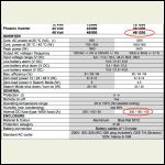
victron.jpg
| 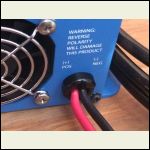
image1.JPG
| 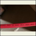
image2.JPG
|  |
|
|
bronco_ed
Member
|
# Posted: 26 Sep 2017 02:15pm - Edited by: bronco_ed
Reply
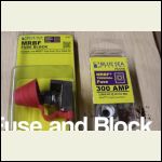
Here is a snapshot on how it is located on busbar...
Per Ontario Lakesides youtube video...
Again trying to understand how system works ;)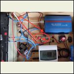
component_wiring.jpg
| 
Fusebock.jpg
|  |  |
|
|
bronco_ed
Member
|
# Posted: 26 Sep 2017 03:02pm - Edited by: bronco_ed
Reply
Maybe that is the wrong fuse shown and should display a 30 amp?
I doubt it... looking at Creeky's site he says "300 amp fuse" is included in his kit
Since all wires are heavier on the bus bar would it be to isolate a faulty inverter from harming the rest of the system?
|
|
sparky30_06
Member
|
# Posted: 26 Sep 2017 03:17pm
Reply
Oh forgot to add length of wire also. If you are running in free air then ampacity does go up
|
|
|
bronco_ed
Member
|
# Posted: 26 Sep 2017 03:33pm - Edited by: bronco_ed
Reply
Free air? Set up will be similar to photo above however battery will be located in separate compartment with heater. I do not plan on adding any length to the standard 1 meter wire that is on inverter...
|
|
razmichael
Member
|
# Posted: 26 Sep 2017 04:02pm
Reply
Are you/me mixing up wire gauge vs cross section? Your model Inverter says 10mm cross section which is 3/0 gauge (48 volt for 1200 inverter). You should check as 10 gauge is way too small for the inverter. Hoping you mean 10mm cross section
|
|
bronco_ed
Member
|
# Posted: 26 Sep 2017 04:38pm - Edited by: bronco_ed
Reply
I have shown a picture of the wire that came prewired on the inverter... I see AWG 10 (above)
Below is the wire next to a 4AWG and 6AWG it is definitely smaller.
So I believe I am reading the wire correctly.
I have only read good things about the inverter.
I found this chart seems to me 48v is a different animal?
Says a 48v system can handle 50 amps 2400 volts for a length of 22 feet.
all with 10 gauge wire.
Although this still does not answer my question about proper fuse size.
|
|
ICC
Member
|
# Posted: 26 Sep 2017 05:38pm
Reply
Amps are amps, no matter the voltage. But 30 amps at 12 volts = 360 watts whereas 30 amps at 48 volts = 1440 watts. So, yeah if the inverter watts are under 1440, the 10 gauge is fine. But it still should not have a 300 amp fuse between battery and inverter.
|
|
bronco_ed
Member
|
# Posted: 26 Sep 2017 05:42pm - Edited by: bronco_ed
Reply
If the inverter wires are 10 gauge and the inverter is capable of Peak power of 2400 (surge?) How does that work out?
Also can you point me to formula for proper fuse sizing or chart for my situation?
Thank you for your feedback
|
|
bronco_ed
Member
|
# Posted: 26 Sep 2017 05:54pm - Edited by: bronco_ed
Reply
Never mind on the 2400 surge... The chart answers the question. 
|
|
bronco_ed
Member
|
# Posted: 26 Sep 2017 06:07pm - Edited by: bronco_ed
Reply
I found this table on line and used it backwards (filling in the amps until I got to the wire size attached to the inverter) to find out what the wire was capable at 1 meter.
If I stay under the 175 amp I should be OK. (i.e. fuse at 150 amps the one wire attached to the fuse should be protected)
Would you folks agree?
Thanks
(ps 150 amp came to 11 gauge so one size smaller)
|
|
bronco_ed
Member
|
# Posted: 26 Sep 2017 07:11pm - Edited by: bronco_ed
Reply
Just throwing this out there...
Since there are two wires on the inverter would that mean 150 amp per wire thus the reason for the original 300 amp fuse?
Thanks
|
|
creeky
Member
|
# Posted: 27 Sep 2017 06:17pm
Reply
Fuses are designed for protection. I use 300 amps on a few of my systems for a variety of reasons. Note, the sizing varies with voltage and system size.
Basically you want your fuse to be high enough that you don't trigger it with day to day operation
(ie. 125 amp surge with a compressor starting) but still low enough that a "holy *^E" moment trips the fuse.
The amps carried by the wire etc is irrelevant as the high surge lasts for milliseconds before the fuse trips.
REMEMBER: SAFETY FIRST is the most important thing. Safety of your Family. Friends. You. Even your dog. I draw the line at cats (kidding).
Do your due diligence. Study. Learn. Understand.
I do worry that a little knowledge can be a dangerous thing. If you're going to copy my systems (no worries!). Please make sure everything is identical. The problem here is the number of variables. And each variable changes the structure.
Good luck. It is a fun hobby.
|
|
sparky30_06
Member
|
# Posted: 28 Sep 2017 06:52am
Reply
creeky
slow blow & fast blow isn't that why the type of fuse plays a factor also and inrush current
|
|
creeky
Member
|
# Posted: 28 Sep 2017 08:30pm
Reply
exactly.
|
|
NorthRick
Member
|
# Posted: 29 Sep 2017 05:02pm
Reply
Quoting: bronco_ed I found this table on line and used it backwards (filling in the amps until I got to the wire size attached to the inverter) to find out what the wire was capable at 1 meter.If I stay under the 175 amp I should be OK. (i.e. fuse at 150 amps the one wire attached to the fuse should be protected)Would you folks agree?
I would not agree. I wouldn't put a fuse bigger than 30amp on a circuit using 10 gauge wire.
|
|
bronco_ed
Member
|
# Posted: 29 Sep 2017 07:49pm - Edited by: bronco_ed
Reply
If anyone is interested.. This chart was also interesting... It shows how many amps it takes before a particular gauge wire will melt... Insulation is not taken into consideration in the chart.
|
|
creeky
Member
|
# Posted: 2 Oct 2017 06:50pm
Reply
I will add. The 300 amp fuse in my systems is attached to the battery combiner headed to the inverter.
If anyone wants to have a look at the system you can see it at my website. bobolinksolar dot com
there is also a "simplified solar designer sheet" FREE you can download. no address etc required. you will see how a system goes together. And note how the relationships of amps/watts/voltage all fit together.
Bronco. That chart was neat. the fuse is for safety. it will trip in milliseconds. so. pretty cool.
|
|
|

