| . 1 . 2 . >> |
| Author |
Message |
smallcabin
Member
|
# Posted: 5 Oct 2015 02:54pm - Edited by: smallcabin
Reply
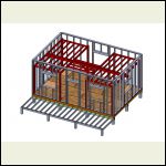
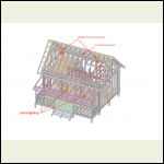
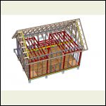
How would you run cables to the outlets and lighting in this diagram? Rough locations and types of amperage usage.
**Note: I'm more of a visual person....so please feel free to illustrate line drawings to indicates route of cables.**
Also...Cabin does not have flush toilet and running water. The only large appliances are an electric stove and small frig...and maybe a wall hanging AC.
Your help is appreciated it.
Thanks!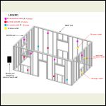
Walls_AssemblyA.jpg
| 
Walls_AssemblyB.jpg
| 
Second_floor_ligthin.jpg
|  |
|
|
MtnDon
Member
|
# Posted: 5 Oct 2015 03:21pm - Edited by: MtnDon
Reply
You need a how-to book. Maybe this one? There are many. I just picked that one at random as I do not have a specific recommendation.
If you are really NOT knowledgeable about electricity you may very well be safer hiring an electrician.
There are many things to watch for... holes thru studs to run wires at proper setback or faced with steel plate, for starters. Staples at the correct spacing (to secure the wire runs), and more. It takes a book, more or less, to cover all the answers.
Question 1... Will this be inspected? It should be wired up to NEC standards even if it is not. That's for the safety of anyone who happens by including yourself, family, etc. Many of the common code needs are addressed in a good DIY book.
Question 2... The 30 amp outlets are puzzling me. Those are rare in a cabin. Normally they ate only used on large appliances like clothes dryers, big air conditioners, etc. Normal receptacles are 15 or 20 amps.
|
|
smallcabin
Member
|
# Posted: 5 Oct 2015 03:35pm
Reply
Thanks Don,
I've been reading and watching youtubes for the last couple months. Of course, I want the work to be within regulation/code.
To your concern on Q.2. Would you suggest I go with 20 amps?
|
|
MtnDon
Member
|
# Posted: 5 Oct 2015 04:22pm
Reply
Quoting: smallcabin To your concern on Q.2. Would you suggest I go with 20 amps?
If you don't plan on an appliance that requires 30 amps, it is a waste to install those, IMO.
Quoting: smallcabin I want the work to be within regulation/code.
Are you grid tieing? If so have you asked the power company what they require from you before installing new grid service.
Quoting: smallcabin youtubes
There's as much bad info on youtube as good info. Be careful, cautious of what you believe.
|
|
Steve_S
Member
|
# Posted: 5 Oct 2015 06:47pm
Reply
Electric's are not something to "guess at" and as MtnDon says, the stuff on Youtube "can" be good but a fair bit of it is kludged and I've seen some outright scary things done on Youtube Videos with electrical.
Inspected Electrics must be checked at Rough-in prior to connection. I believe this is pretty universal.
Insurance Company Requirements... The Nasty beasts... Certified electrical installation only, else you won't have insurance... if you try to fudge it, well, let's just say DON'T !. Ohh the fine print get's ya every time !
Get a hold of a Electrical Code book for your State. Sometimes they just have an addendum to the NEC for the States. Tad different here in Canada.
There is a Series of Books called "The Electrical Code Simplified" published by P.S. Knight Publishing. They do them here in Canada for every Province/Territory but I believe they also do a series for the different states. This Guide is GOLD !
*-*-*-*-*-* low techno babble section *-*-*-*-*-*
Typically standard circuits are 120v/15a with a maximum of 10 devices. Plug, Switch, Light fixture = a device. Recommended load max is 8 for margin.
Kitchen:
Split-Plug 15a using 14/3 wire (2 hot, 1 neutral with two 15a breakers @ panel). (This is now disallowed in some regions). There is only 1 plug per Breaker.
Single 20a uses a 20a breaker to a "single" plug in the kitchen. This is to accommodate High Draw kitchen appliances. 20a requires 12/2 Wire.
Kitchen Stove: 240V/25A-30A. Gosh I hope this isn't on Solar. 1 outlet per breaker set. Run length will determine wire size & depending on routing the casing type as well.
EXTERIOR: Careful here, there's some gotcha's lurking.
Circuits must be CGFI ! Easiest to do @ Breaker Panel with CGFI Breaker (they ain't cheap but best solution). These are typically 15a circuits. Exterior Lights (porch) should also run from this circuit.
Washroom: MUST BE CGFI ! No if's ands or but's on this. The single Fastest way to get electrocuted ! Can be accomplished by using a CGFI plug @ entry which then goes to feed light switch & fan. Bathroom should be a separate circuit, CGFI breaker can be used as well.
Window AC: Almost all are designed to work on a shared 15a circuit. Additional amperage capability is not warranted. If you have a unit that demands 20a, seriously consider shopping for a new one. Even my 10kBTU Portable Commercial AC is 15a.
SIDE NOTE ON COSTS: Std 15a circuits use 14/2 wire, this is the cheapest. Split Plugs use 14/3 wire, still cheap but getting up there. 20a circuits are 12/2 bigger copper more $, 115v/30a 12/2 or 10/2 depending... 240v/30a ouch on copper. This will be minimum of 10 guage or 8 if your running long. _AND_ the fugly...
15a plug will not handle 12guage wire,
20a plug is designed for 12 not 14.
Buying individual plugs, switches and mixing types get's $ quickly. Buying a bulk pack of 10 plugs is usually 25% cheaper. Not much at first glance but at the end of the project it can be a headslap moment of realization.
I can diagram it out for you roughly BUT I'm not sure I want the implication... unless it's more or less a doodle that you can't present to an inspector. That whole feeling responsible if something goes amiss thing.
There is a lot of things to factor in there.... for example.
All wall plugs must be min. 12" off floor surface, wall switches STD must be at 50" from floor _or_ 36 for accessible. Switch Placements for interior & exterior & stairwells / hatchways.
Exterior plugs have to be in waterproof boxes and covered. Plugs / switches inside located on an exterior wall have to be on the "warm side" of the vapour barrier and the "device boxes" themselves must be in a vapour barrier or sealed per code (this varies a bit).
I know this is a tad wordy and made you look at it and grumble considering you asked such a simple innocuous question. Sorry about that but I'm hoping that I made you aware of potential things and time to ponder on it.
That B&D Book MtnDon suggested is pretty good, I have that one too, well dog eared BUT it's pretty general so you want to ensure you are within local compliance.
Hope it helps
Steve
|
|
bldginsp
Member
|
# Posted: 5 Oct 2015 08:00pm
Reply
If you do it yourself, spend a lot of time beforehand learning. The book Don recommended looked good, there are numerous other books that focus on residential wiring specifically, get several of these and read until it gets redundant. Don't try to tackle the whole NEC, there is a lot in there you don't need. Excuse me for saying so but you have shown your ignorance already with what you have said to us.
Most of the cost of hiring an electrician to do the work is in the labor of pulling wire and making up panels and outlets. This you can do yourself. What I'm thinking is if you could get an experienced contractor or electrician to help you at the start and then check your work, you'd get it done for less with the oversight of experienced eyes.
1-sit with a contractor and determine the number of circuits, the ampacity of each, required wire size, location of outlets, size and location of main panel etc.
2-armed with this knowledge pull the wire for each circuit and locate all outlets and the panel, by yourself
3-have the contractor help you double check the work and make up panels and outlets.
The money it costs will buy you peace of mind.
|
|
Borrego
Member
|
# Posted: 5 Oct 2015 09:57pm
Reply
To add to Steve_S:
1) GFCI's are required at all kitchen outlets as well as bath, laundry, exterior, anywhere there is water.
2) Code says 2 separate 20A circuits for kitchen counter appliance circuits.
3) GFCI's are allowed on a bath lighting circuit, but usually not recommended for obvious reasons...
4) Most jurisdictions don't allow appliances plugged into GFCI's
5) I recommend separating the outlets and switches - do some research...
6) Most importantly, what about bonding and grounding at your main panel? 2 ground rods are typical now, you can use 1 if the amperage is low enough but with the expense to test it, it's easier to put in 2
7) Solar and generator tie ins get complicated, but there are some smart guys on here, ask away!
8) bldginsp has a good idea - get someone to lay you out, you do the grunt work, they come back to check....generally speaking electrical is not smart to mess with unless you're good. It isn't like other trades where stuff just comes apart or falls down, in this case people get killed. I wouldn't think you'd want that on your head just for a few dollars...
|
|
toyota_mdt_tech
Member
|
# Posted: 5 Oct 2015 10:34pm - Edited by: toyota_mdt_tech
Reply
15 amp outlets, use 14AWG (white in color) wire (can use 12AWG (yellow in color), much harder to work with) but never visa vera, ie 14AWG (white wire) on a 20A breaker and I'd keep lighting on its own 15 amp circuit. I'd use a separate circuit for upstairs outlets (15A) and a separate one for downstairs. I'd run a separate circuit for kitchen outlets. 30 amps will be on their own circuits, you will use 10AWG wire (orange in color now)
Lighting uses their own 15A circuits. Anything outside, kitchen, bathroom, garage or wet areas required GFCI system.
An electric range/cooktop + oven) is usually a 50A circuit, this would be 6AWG wire. 30A for a dryer, 30A for electric hot water tank (orange wire).
Drill holes in center of studs, so siding or drywall nails cant penetrate it. Dont ever drill through a joist or rafter at the edges of the boards (edge, not end), always in the center. And drilling in the end is fine over a wall or close to a wall. Make your runs efficient, to use the least in length, but there is other considerations too.
I'd never drill through an engineered truss.
Stairs? You will need a pair of 3 way switches for that. One at the bottom, another at the top.
Rule of thumb:
15A means 14AWG wire ( up to 10 outlets)
20A means 12AWG wire, yellow in color.
You can install 15 amp outlets on a 20A circuit. The outlet is the current limiting factor by design. And if you do this, you can use as many as 13 outlets per circuit. I wouldnt do this in a garage or kitchen area where there may be lots of high demand appliances, ie toaster, hot plate, waffle iron etc. More for bedrooms etc.
Design each circuit to be well under max, just use more circuits from panel (breakers) then its safe to expand later.
Garages, outlets must be high up, romex staple to secure wire withing 4" of the box. Measure outlet boxes, keep them consistent. I like 14". Switches, keep them all the same. I like 48", this seems to be std. This will be the same for counter top outlets in a kitchen too.
Tying grounds together in a box on an outlet run, there is several ways. Leave plenty of pigtails. I like no less than 12" out the box in line (in) and load (out). Are you running any ceiling fans, ie dual function like a light with a fan? If so, run the romex with the extra wire (extra red inside AKA 14-3 W/ground)
This is also required between 3 way switches. Otherwise, 12, 14-2 W/ground is all you need. Some 220 V outlets may need 4 wires also, if on doubt, run 4 wire for these. Then you can ignore the extra wire vs trying to run it after sheetrock is all in place.
|
|
|
NorthRick
Member
|
# Posted: 6 Oct 2015 12:38am
Reply
So, not an electrical comment, but your framing drawings show the beam for the loft being supported by the window ledger on each end of the cabin. Generally not a good idea.
|
|
Don_P
Member
|
# Posted: 6 Oct 2015 07:56am
Reply
Quoting: NorthRick your framing drawings show the beam for the loft being supported by the window ledger on each end of the cabin
...and no other support inside that I can see, probably overspanned as well.
Not giving advice for fear of liability is sort of interesting. There is no expectation on the internet of correct advice, heck we have a turnipseed running around the forums looking to have someone, anyone, validate his latest hairbrained idea. Someone will, that does not make that person liable for turnipseed's failings.
|
|
creeky
Member
|
# Posted: 6 Oct 2015 10:29am
Reply
Quoting: Don_P we have a turnipseed running around the forums looking to have someone, anyone, validate his latest hairbrained idea

|
|
Borrego
Member
|
# Posted: 6 Oct 2015 10:46am
Reply
Quoting: NorthRick but your framing drawings show the beam for the loft being supported by the window ledger on each end of the cabin. Generally not a good idea.
Good catch, I was just looking at the electrical! "Generally not a good idea", funny! You want binding windows, here they are...The entire floor being supported off the walls is not great either, although I suppose there won't be much load on a loft...but hmmmm....
Well hey we're just trying to help each other out and a lot of us have many years of experience, but maybe some people shouldn't be building their own cabins...?
|
|
smallcabin
Member
|
# Posted: 6 Oct 2015 04:51pm - Edited by: smallcabin
Reply
Steve, Toyota, Borrego, Bldginsp, and MntDon....
Thank you for your inputs...they're very informative. Indeed, I have much to digest and lots of learning to do. Of course, I will have help when the time comes to run electrical. However, I believe asking questions is part of the learning process if you want to learn anything? So don't mind if the questions seem to be rather "naive" in nature. It wasn't meant to be.
As to the concern of Northrick's comment....The center beam has a 6x6 support post in the middle of the beam, which the drawing may not have clearly illustrated. It's rock solid and of course, it did pass inspection. 
Thanks!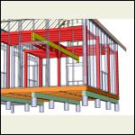
support_beam.jpg
| 
support_beam2.jpg
|  |  |
|
|
Steve_S
Member
|
# Posted: 6 Oct 2015 06:09pm
Reply
@Smallcabin. There is one thing I am adamant about and repeat often to one & all... The only "stupid question" is the one you do not ask ! Never be afraid to ask questions and seeking opinions on various is good for "sanity checks".
I'll recommend this site house-improvements.com . They have great info, good videos on many topics & how-to's (complete with Shanon's Canadianism's) but they explain everything very well (tad long winded at times). He even covers things that most "assume" and assumptions can be quite problematic as you know.
|
|
bldginsp
Member
|
# Posted: 6 Oct 2015 07:50pm
Reply
smallcabin- yes it's good to ask questions and sounds like you are on the right track. I hope you base your work on more than just the good advice you've gotten in this thread, because electrical has a lot of pitfalls. It's fairly simple, but also easy to blow and blow badly. Research til the research is redundant. Good luck
|
|
smallcabin
Member
|
# Posted: 7 Oct 2015 01:28pm
Reply
In the state of WI...what am I responsible for as far as meter socket and post? Are these items owner's responsibility or electrical company?
thanks!
|
|
Borrego
Member
|
# Posted: 7 Oct 2015 01:42pm
Reply
You will probably have to provide the main panel box or duplex box, the pipe and mast head to above the roof line, and all appropriate wiring to that point. The utility will do the hook-up from there. I would call and ask them as jurisdictions vary and we on this forum are just guessing....
Regarding your beam drawing...regardless of the center support post there will still be some weight bearing on the center of those window headers. Unless you've already built this (?) I'd change that for sure...
|
|
smallcabin
Member
|
# Posted: 7 Oct 2015 05:30pm
Reply
thanks Borrego...I'll call and ask.
YES, already built it like so. And YES....the window's headers will bear some "small" weight....but not the majority of the weight...and with that, I've sized the window headers with 2x10's and double the window's trimmer studs. NO SAGGING showing so far...knock on wood. 
|
|
bldginsp
Member
|
# Posted: 7 Oct 2015 06:31pm
Reply
Utility companies always have their own specific rules for the connection of the service enclosure. You buy it, but install it according to their rules. They should have a book of instructions, or if you are lucky, someone will come out beforehand to look at it with you.
But usually the building department must first inspect the electrical connections in the service on the circuit breaker side of the box, along with all the wiring in the house. Basically, the utility won't hook up the power until they know that the building department has verified code compliance with whatever it is that the service will be powering up. The building department inspects from the meter to the house, the utility inspects from the meter toward the transformer.
Call the building department and ask what requirements they have for issuing a meter release. They will inspect and then somehow let the utility know that they have passed it. Then you can schedule with the utility to hook it up.
|
|
Don_P
Member
|
# Posted: 7 Oct 2015 07:35pm
Reply
Quoting: smallcabin YES, already built it like so. And YES....the window's headers will bear some "small" weight....but not the majority of the weight...and with that, I've sized the window headers with 2x10's and double the window's trimmer studs. NO SAGGING showing so far...knock on wood.
I've "bridged" over like this many times. Here's how to quickly check it;
From the drawing it looks like about 32 square feet of loft supported by the header @40 lbs/SF...~1300 lbs
Using a beam calc or the center point loaded beam equations in the Beam Equations book at awc.org
The header hit's its' limits at about 4500 lbs, I think you're good there. Checking the jacks for crushing into the header then underfloor would be the next places to check. That is all part of the checks during design to confirm a "continuous load path".
This header is kind of neat in how it fails. I checked a 39" span using generic numbers around the SPF strength range. The header fails at about 4500 lbs of center point load in both bending and in horizontal shear, sort of unusual. At that point it has only sagged about 20 thousandths. For a short, heavily loaded beam the wood will probably actually fail at the point where sagging comes into play.
|
|
NorthRick
Member
|
# Posted: 7 Oct 2015 08:16pm
Reply
On the beam resting on the headers comment. Just wanted to point that out in case you didn't understand how loads in residential structures work (lot's of folks don't have a clue). You can make it work, and sounds like you have, but my preference would be to not place a load over an opening if you can design around it.
|
|
Borrego
Member
|
# Posted: 7 Oct 2015 09:14pm
Reply
It just ain't right...
|
|
smallcabin
Member
|
# Posted: 16 Oct 2015 03:28pm
Reply
Just curious.....can I use 15 amps GFCI outlet in all the "regular" outlets...meaning anywhere where there's 15 amps requirement?
makes sense? 
|
|
smallcabin
Member
|
# Posted: 16 Oct 2015 03:30pm
Reply
Looks "RIGHT" to me... lol  
Quoting: Borrego # Posted: 7 Oct 2015 21:14 Reply Quote It just ain't right...
|
|
smallcabin
Member
|
# Posted: 16 Oct 2015 03:36pm
Reply
Tell me...a guy quoted me $3,000 just to run electrical in a 16x24 cabin? Is this average or is he skinning me down to the bone???? When he told me this....I almost have a heart attack!
|
|
MtnDon
Member
|
# Posted: 16 Oct 2015 04:32pm
Reply
Quoting: smallcabin Just curious.....can I use 15 amps GFCI outlet in all the "regular" outlets...meaning anywhere where there's 15 amps requirement? makes sense?
You can, but it doesn't make it safer, only costs more. You only need a GFCI as the first in a chain of other regular outlets.
|
|
MtnDon
Member
|
# Posted: 16 Oct 2015 04:36pm
Reply
Quoting: smallcabin Tell me...a guy quoted me $3,000 just to run electrical in a 16x24 cabin? Is this average or is he skinning me down to the bone????
that's wire, other parts and labor? Also how far a drive from the town/city where he is to your property? As to the price it's so long since I had an electrical quote I have no idea. All I do know is that the very first time I got a quote (on garage wiring) I was also surprised. Same thing (shock) happened when I got a quote for plumbing a new WC, tub, shower and sink 20 years ago. I ended up doing that myself too.
|
|
smallcabin
Member
|
# Posted: 16 Oct 2015 07:26pm
Reply
Quoting: MtnDon that's wire, other parts and labor?
that just labor alone as I told him I'd purchase the materials. Looks like I'll be spending lots of time here asking questions. 
As for the GFCI's....thinks I'll go ahead and use one in every other outlet?
Stay tuned...pictures are coming soon. 
|
|
MtnDon
Member
|
# Posted: 16 Oct 2015 08:05pm - Edited by: MtnDon
Reply
Quoting: smallcabin As for the GFCI's....thinks I'll go ahead and use one in every other outlet?
No, that is not needed. The GCFI outlet has 2 sets of terminals. One pair marked LINE and the other LOAD. The LINE terminals connect back to the service panel. The pair marked LOAD connect downstream to other outlets on thesame circuit. The GFCI protects everything downstream. Place the GFCI in an easy to see location,notbehind the sofa. They have an indicator LED that shows if it is powered.
It is imperative that the wires from the service panel / breakers is connected to the LINE terminals.
One GFCI to be the first device in any circuit that needs protection. That protects the entireline. You can install a GFCI after one ortwo outlets, but thefirst outlets receivenoprotection. OR, use GFCI breakers in the service panel instead.
|
|
smallcabin
Member
|
# Posted: 16 Oct 2015 11:53pm
Reply
Don,
I'm in the process of putting a shopping list together...It definitely makes sense and that would save $$$$ the way you've described it. 
Question on the breaker panel....I bought the QO (Square D) brand. Any thoughts on this?
Good lord....I'm sticker shocked on some of the switches and GFCI outlets ...especially Pass and Seymour brands. OUCH!!!
It's funny....sometimes, i ask myself...Why am I torturing myself with this stupid electrical stuff when I can just keep it "PRIMITIVE"? I guess it gives us a sense of purpose to enjoy life and appreciate the small things that we, at times, take for granted. LOL  
Thanks for the comments....there will be more questions in the weeks to come. Stayed tuned. 
|
|
| . 1 . 2 . >> |

