| << . 1 . 2 . |
| Author |
Message |
Don_P
Member
|
# Posted: 5 Apr 2015 05:51pm - Edited by: Don_P
Reply
It's your call, the triple 2x12's along each side would span 12' carrying the loft/roof but the control is really the lack of footings, your piers are overloaded now.
|
|
mojo43
Member
|
# Posted: 5 Apr 2015 07:57pm
Reply
Thanks for all of the help Don. I am trying to understand how to calculate all of this. How can I figure out how much a 10" 4.5' pier can hold? Also can I calculate the weight of my building?
I had planned to put the deck on 6 posts, but the guys at the hardware place told me that it would be better to use three at the end with a girder. They told me that it would easily hold the weight. Last time I ask for their advice! 
|
|
Don_P
Member
|
# Posted: 5 Apr 2015 09:53pm - Edited by: Don_P
Reply
"Rational design" is a process of quantifying loads, and providing resistance. A simple concept.
It starts with the soil bearing capacity...I used a typical assumption of 2000 pounds per square foot. I don't know where your online codes are, or if they are. The table in the US residential code that describes different soils and their bearing capacities is here;
http://publicecodes.cyberregs.com/icod/irc/2012/icod_irc_2012_4_sec001.htm
Then determine the area of the footing, in this case 10" dia. Area= Pi x radius squared...78.5 square inches. 78.5 square inches/144 square inches per foot = .545 square feet of bearing surface on the soil from a 10" round column. At 2000psf soil each pier is capable of supporting about 1000 lbs, the pier weighs ~1/4 of that already. I typically put a 2'x2' square footing under a deck post, 4 square feet at 2,000psf= 8,000 lbs capacity. This is not a place to skimp. What you find with undersized footings is that most soil has variable capacity and every pier carries a different load, every pier settles a different amount. As that is going on, a truism begins to work, "load goes to stiffness" a high pier on a hard spot under a beam that spans several piers becomes the loaded pier no matter how elegantly the design math might say otherwise.
The 4.5' of burial depth doesn't help appreciably with vertical load but the soil does provide lateral bracing to the pier against wind or earthhquake loads. The amount of bracing provided by the soil is a function of load, soil, depth and area of the pier. Piers fall outside of our prescriptive codes, they require design by an engineer. You are beginning to understand why. A continuous strip footing with foundation walls distributes load better and resists lateral load without having to try to use backfill as bracing.
So we have the vertical capacity of the piers, ~1,000 lbs per pier.
Read back through where I figured the loads before.
Basically a main floor has a design live load of 40psf +10psf dead load (the weight of the materials themselves), these are assumptions, you can google and get lists of weights of materials and get it down to the ounce if you want. The design live load is provided by the code, Table R301.5
For roof, use the horizontal projection for the areas... the bird's eye view. Snow load + dead load, I used your 46 psf LL (snow) +10psf DL, many designers use 15psf DL, something to consider.
Loft floor I fudged and called 15psf LL+10psf DL because a good bit of it is unusable and it looks like little more than enough room to lay down, technically sleeping areas use 30psf LL
That should give you a decent ballpark of loads. Use the method I described before to determine the tributary area and thus load on each pier, for instance a midpier takes more vertical load than say a corner pier. That will get back into minimum footing size as the loads vary per pier. Figure load on the 3 piers under the front of the existing house with the addition also loading them.
|
|
mojo43
Member
|
# Posted: 7 Apr 2015 05:14pm
Reply
Thank you so much for the help Don. I didn't realize all of these calculations were necessary. I didn't even think of it for the first building I built. I wonder now if it is up to snuff?
|
|
Don_P
Member
|
# Posted: 7 Apr 2015 11:19pm
Reply
All these calculations are not neccessary. In the US, and I believe in Canada, the residential codebook is prescriptive. It prescribes methods and materials that are already engineered for oft repeated details. We know they work. As long as someone uses that approach there is none of this, simply follow the text, tables and figures. When you step outside of those prescribed methods then engineering is required. I've explained a bit of the concepts but it would be performed by a licensed engineer. Building entirely on piers is something I would hire an engineer to design. Is the existing building up to snuff, on 10" piers certainly not. In practice I can about guarantee that no one here has had an engineer design their foundation, or any other part of their building. Are they catastrophically failing left and right, no. Do a number of them have problems, sure, Darwin at work on houses.
|
|
ShabinNo5
Member
|
# Posted: 9 Apr 2015 09:10pm
Reply
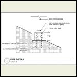
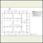
I guess we are the exception. Our Shabin plan included adjustments by a structural engineer. He was quite excited about the challenge of wind and snow loads on the exposed hill side. In the end the Shabin is supported by 18 piers. For us the cost was worth the peace of mind.
|
|
Don_P
Member
|
# Posted: 10 Apr 2015 07:05am
Reply
Would you mind sharing the foundation details?
|
|
mojo43
Member
|
# Posted: 10 Apr 2015 07:32am
Reply
How big is the structure? I have am planning to put the extra posts in this weekend. Thanks for all of the help Don!
|
|
|
ShabinNo5
Member
|
# Posted: 10 Apr 2015 05:03pm
Reply
Our thread: http://www.small-cabin.com/forum/6_618_0.html#msg23924
The big change to the original plan was to convert a 6 X 20 section of the deck to interior space. Overall the full structure is 26 X 20 including the covered deck.
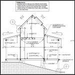
Don_P... In our case each pier is attached directly to bedrock. The deepest we had to dig down was 30 inches. So I will admit that many of the concerns about stability are mitigated as the bedrock is serving to stablize the piers.
Foundation_Pier_Deta.jpg
| 
Foundation_Piers.jpg
| 
Framing_Notes.jpg
|  |
|
|
Don_P
Member
|
# Posted: 10 Apr 2015 07:41pm
Reply
There we go, 3rd detail "Framing_Notes", building posts to extend from footing to eave... he is using the building to brace the posts, I fully agree. This removes all those points of potential rotation. And yes, nothing like bedrock for a foundation. Thanks!
|
|
| << . 1 . 2 . |

