|
| Author |
Message |
rockies
Member
|
# Posted: 6 Sep 2013 09:04pm
Reply
This is a pretty simple shaped cabin I am planning to build in the Canadian Rockies. It's 18 feet wide by 26 feet long with 12 foot high walls all around supporting a 12/12 pitched gable roof. The roof is cut back to the exterior wall on the south side to allow for the attachment of a future screen porch roof. The exterior walls (grey) are standard 2x6 studs with 1/2 inch sheathing and 1/2 inch drywall. On the exterior is a further layer of 2 inch foamboard under the siding for extra insulation, but that could be omitted. In the sections the doors are shown installed 6 inches above the main sub-floor (windows are installed at 86" above the sub-floor) to allow for a 6 inch deep false floor to be installed throughout. This false floor allows me a place to put any plumbing pipes and electrical wiring and prevents me from worrying about the pipes freezing in the winter. The interior walls (yellow) are 2x4 construction with half inch drywall on both sides. All dimensions are to the stud layer. The loft floor and the cross beam (dotted line) are tied into the long side walls at a standard 8 foot ceiling height and help to provide cross bracing. The loft level has a sleeping area above the mudroom, and there are two storage areas as well (one over the part of the bathroom, the other over the office area). The entire cabin and the future screen porch will be built on pier foundations with wooden support beams. Heating, hot water, bulk storage and the laundry will be contained in a small out-building nearby. All the water used in the cabin will be heated using a "Profab" indoor furnace and the pipes for hot water and radiant floor heating will run into the cabin inside an insulated chase. Fiberglass framed Milgard windows and doors, Hardie Panel siding and Galvalume standing seam metal roofing.
This is about as big as I want to go for a cabin, and yet there is a lot of usable space inside: full sized bathroom, full sized kitchen appliances, mudroom, office area, large livingroom/dining, pantry cabinet and a bedroom loft for a queen sized bed. The bedroom closets are on either side of the built-in sofa, and the dresser is under the sofa seat. The "office" room north of the kitchen could be used as a dressing room or closet as well.
Please let me know what you think or if you have any suggestions or questions.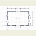
basic shell floorplan
| 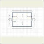
basic shell loftplan
| 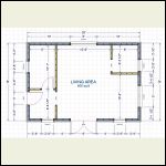
basic shell framing
| 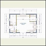
finished cabin floorplan
|
|
|
rockies
Member
|
# Posted: 6 Sep 2013 09:06pm
Reply
sections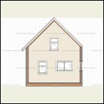
section east
| 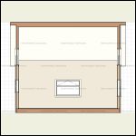
section north
| 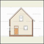
section west
| 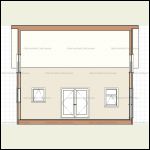
section south
|
|
|
rockies
Member
|
# Posted: 6 Sep 2013 09:07pm
Reply
elevations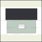
north elev
| 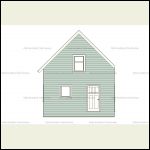
west elev
| 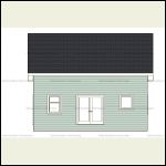
south elev
|  |
|
|
rockies
Member
|
# Posted: 6 Sep 2013 09:08pm - Edited by: rockies
Reply
Here is the plan with the screen porch attached and a small south east corner deck that is also covered with the porch roof. The roof slope is 4/12
|
|
rockies
Member
|
# Posted: 6 Sep 2013 09:10pm - Edited by: rockies
Reply
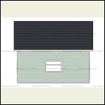
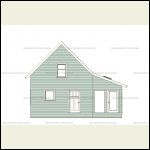
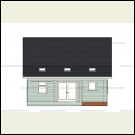
I'll post some finished interior drawings later. Here are the elevations with the porch attached. There will be a small shed roof over the door on the west Elev with a deck and support posts (not shown)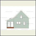
East Porch Elev
| 
North Elev
| 
West Porch Elev
| 
South Porch Elev
|
|
|
MtnDon
Member
|
# Posted: 6 Sep 2013 10:15pm
Reply
Quoting: rockies The exterior walls (grey) are standard 2x6 studs with 1/2 inch sheathing and 1/2 inch drywall. On the exterior is a further layer of 2 inch foamboard under the siding for extra insulation
Great idea IMO, but... For the climate zone 2" of foam may not be enough to prevent moisture condensing inside the wall when winter turns its coldest. There is an article on greenbuildingadvisor.com that covers this very thing. Calculating the Minimum Thickness of Rigid Foam Sheathing The article is USA focussed but FYI all of Montana and the tip of Idaho are zone 6... calling for R15 of foam with 2x6 framing and the stud bays are filled with something like fiberglass or rock wool.
~~~~~~~
I would re-think the 12 foot walls with the loft floor at the 8 foot level. Reason? If the roof is framed with conventional rafters the outward forces on the wall tops from the roof loads can get to be very large. With the loft floor joists restraining movement at the 8 foot mark the rafters will be pushing out on a 4 foot lever (upper wall studs). No engineer I know would pass that wall design.
A better choice would be a structural ridge beam. This would have supports at each end going down to the foundation footings at or below frost depth. At 26 feet overall length a midpoint post with the same foundation would cut down the size and expense of the ridge beam.
Another solution would be to frame the main floor at 8 feet and build an upper floor on those walls. Then use something like 5 foot walls on the second story. Use rafters with the rafter ties raised to the maximum approved height of 1/3 up the lower section. See here for a clarification on the rafters and rafter ties.
Is there a building dept involved? Permits? Pier foundations do not meet the IRC, the code used in all but 1 US state. Not everyplace enforces the IRC so you do see many projects that do not meet codes.
|
|
rockies
Member
|
# Posted: 6 Sep 2013 11:12pm
Reply
Hi, thanks for responding. There will be a ridge beam in place holding up the roof but I'm not sure how the framing will work in the gables to support it because of the loft windows. I figured that having the walls rise to 12 feet and then tying the north/south walls together with cross beams at the 8 foot level would create a bracing structure like a capital "H" (in section) and avoid the scenario of having short upper stud walls being pushed out by lateral forces. The other possibility is rather than having a stick built roof using a SIP panel roof instead (12 1/4 inches thick) resting on the 12 foot walls and a ridge beam. I don't think there would be too much lateral force with that, but I'm still doing research. The walls may be better insulated with a spray foam on the inside of the wall cavity and then batt insulation, but would the rigid foam still be necessary on the outside? Thanks.
|
|
MtnDon
Member
|
# Posted: 6 Sep 2013 11:33pm
Reply
Quoting: rockies The walls may be better insulated with a spray foam on the inside of the wall cavity and then batt insulation, but would the rigid foam still be necessary on the outside? Thanks.
I like exterior foam insulation/sheathing as it is often less costly than spray foam; sheet foam = DIY and spray = paid installer. But spray in the walls, thick enough to avoid the condensation issue, then batts works. IMO, you can get more R with exterior foam sheets. (I have retrofitted a couple of exterior walls that way. More work around windows and doors mind you. But also air tight and can be built as a rain screen wall.
~~~~~~
You can trace the load down from the ridge beam around windows by using properly sized headers above a window or door and splitting that down two post supports to the foundation. On the east wall you would have to move the one main floor window to make a simple 2 path from upper window header straight down. Some changes around the door on the west end. Or the load can be split into three but then the calcs get more complicated.
Which raises the question of what is the plan for the foundation support for the ridge beam?
How much snow load?
Because of the length, and no mid supports I assume a manufactured/engineered beam would be used. No mid supports shown in drawings.
~~~~~~
If you do a true ridge beam there are zero outward forces on the wall tops so there is no problem with outward wall forces then.
|
|
|
MtnDon
Member
|
# Posted: 6 Sep 2013 11:37pm
Reply
Quoting: rockies ridge beam. I don't think there would be too much lateral force with that
The whole point of a structural ridge beam is that there are only vertical loads down to the foundation; half the load on the ridge beam and its supports; 1/4 on each side wall. Straight down, no horizontal vectors at all. No outward wall forces.
|
|
rockies
Member
|
# Posted: 7 Sep 2013 06:42pm - Edited by: rockies
Reply
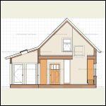
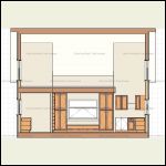
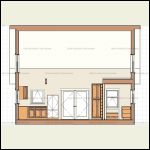
Here are the sections with the porch attached. The next two sections also show the ridge beam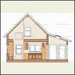
Section East
| 
Section West
| 
Section North
| 
Section South
|
|
|
rockies
Member
|
# Posted: 7 Sep 2013 06:44pm - Edited by: rockies
Reply
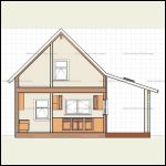
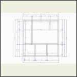
Here are the sections through the mudroom/bathroom and the office/ kitchen. Also the foundation plan for the entire cabin, which will be concrete footing tubes down about 5 feet capped with wooden support beams under the exterior walls and supporting the main interior walls. When I contacted a SIP manufacturer (Insulspan) they said that a 10 inch roof panel was enough for the snow load (88 lbs/ square foot) but I would rather do the 12 inch panel. It will cost about $6000 for the roof, but then there will be no issues with ventilation, vapour barriers, etc. Just seal the joints properly and add a cold roof above the SIP.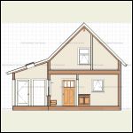
Mudroom/Bathroom West
| 
Office/Kitchen East
| 
Foundation Plan
|  |
|
|
MtnDon
Member
|
# Posted: 7 Sep 2013 08:07pm - Edited by: MtnDon
Reply
Looking at the general main floorplan.... to me while it is nice to have suuficient counter space in a kichen, it is too spread out. Fridge and range are many paces apart; too much walking for my likes. But I do like counter space. I'd do a U-shape with longer side arms and a shorter connecting counter (where sink is).
Clarify something about the foundation plan if you will... are the perimeter and interior shaded areas a continuous poured concrete footing, at 5 feet deep?
The SIP roof panels can be a very good way to get a well insulated roof. 
|
|
rockies
Member
|
# Posted: 8 Sep 2013 06:25pm - Edited by: rockies
Reply
Hi, I used a book I bought years ago when I was studying architecture that used different body shapes and sizes to design interiors for proper functions. They calculated the minimum and maximum heights, depths and widths needed for proper placement of appliances, windows, countertops, staircases etc so that the greatest variety of people could use them comfortably. Based on that I laid out the kitch so that there was sufficient room for prep, clean-up, cooking, etc, and 18 inches was the minimum needed next to a sink. So a 30 inch wide cabinet, plus 18 inches each side, and then the 2 foot deep side cabinets came out to 9'6". Plus you have to allow for movement in the work zone when the oven door is open, or two people are working. Still, in a 60 sq foot kitchen there is lots of room for 2 people to work.
The shaded areas in the foundation are the wooden beams. The small round circles represent the concrete piers. Unfortunately the trial version of the software program I used doesn't let me design a true pier and beam foundation, so it all looks like concrete.
|
|
MtnDon
Member
|
# Posted: 8 Sep 2013 07:32pm
Reply
Quoting: rockies ... lots of room for 2 people to work
There ya' go. I'm a 1 person in the kitchen, 2 is too many, kind of a cook. 
Quoting: MtnDon Clarify something about the foundation plan if you will... are the perimeter and interior shaded areas a continuous poured concrete footing, at 5 feet deep?
????
|
|
rockies
Member
|
# Posted: 9 Sep 2013 07:13pm - Edited by: rockies
Reply
The name of the book I used for design was Human Dimension and Interior Space. http://www.amazon.ca/Human-Dimension-Interior-Space-Reference/dp/0823072711
The authors calculated the space needed for every type of function in a home, office, retail store, etc. so that 95% of the population could use those spaces without being cramped or having to strain to do things. It's an older book but extremely helpful for laying out kitchens, bathroom, bedrooms, stairs, etc
|
|
MtnDon
Member
|
# Posted: 9 Sep 2013 11:21pm
Reply
Interesting book.
I'm still curious about the foundation though. I may be misinterpreting what some of the grey parts are in the drawing. Attached is a drawing I marked up with my question.
Thanks
|
|
rockies
Member
|
# Posted: 10 Sep 2013 08:23pm
Reply
Hi MtnDon, all the grey areas (and the areas you've marked in red)are wooden perimeter beams, probably 6 to 8 inches wide and 8 to 10 inches deep, depending on what I need to support the cabin. The circles under the beams are concrete piers, one foot in diameter and going into the ground about 5 feet. The cabin will be up off the ground between 18 inches and 2 feet. The "Chief Architect" program I use doesn't let me design a pier system, so all the beams look like concrete. The beams and piers are located to supports the main floor exterior and interior walls and the major point loads for the cabin and the screen porch. By the way, the book may be available as a free download pdf. Search in Google.
|
|
rockies
Member
|
# Posted: 18 Jan 2014 04:28pm
Reply
Hi. I posted this a while ago ,but there are cross beams on top of the walls between the bathroom and livingroom and the office and the livingroom at the loft level. Support posts can come down from the overhead ridge beam to rest on these two beams. I think that will provide the necessary support for the roof and transfer loads to the ground sufficiently.
|
|
|

