|
| Author |
Message |
paulz
Member
|
# Posted: 14 Feb 2018 08:42pm
Reply
Got a couple of Mule 500 gate openers, nothing else. I want to test them but can't find what all these dang wires do. There's a thicker red and black, then 5 smaller ones. Any idea?
|
|
darz5150
Member
|
# Posted: 14 Feb 2018 09:07pm
Reply
I would think the other wires go to the control box to open/close. Even if you have remote controls, something has to receive the signal and flip the correct relays to tell the actual motor what to do.
|
|
paulz
Member
|
# Posted: 14 Feb 2018 09:35pm
Reply
Yes that's what I think. These are 12vdc right? If I had to guess, I'd hook the large red and black to 12vdc and touch the other wires to the + and see what happens. And watch the smoke probably...
|
|
darz5150
Member
|
# Posted: 14 Feb 2018 10:01pm
Reply
Can you get a model # and do an internet search for a manual. I blew up your picture and saw it was mighty mule. I found one on amazon and it was 12 volts. But that doesn't mean that's what ya got. Do you have the actuators or any other parts/pieces?
You may just have a transformer that changes voltage from ac to DC. Not really sure tho.
|
|
paulz
Member
|
# Posted: 14 Feb 2018 10:12pm
Reply
Thanks for the replies. All I have are the two openers that go on the gates. And as the sticker says, Mighty Mule 502. I tried searching online, the install manual is there but it doesn't break down the wiring. The control boxes aren't cheap, I'm not going to buy one without knowing that these things work. There must be a way to test them..
|
|
darz5150
Member
|
# Posted: 14 Feb 2018 10:59pm - Edited by: darz5150
Reply
If you got the actuators, maybe see if the wire colors match up. I would try hooking up the actuators to a battery to make sure they work. If there's only 2 wires on them. That means that switching from open to close (reversing polarity) would be done with the other 3 wires. Are the 5 wires all the same size? The ones going to the actuators would be a larger gauge.
If the actuators don't work. Gate won't work. Game over.
Grab your multimeter, a battery, a cold 6 pack, and a fire extinguisher. Throw everything but the 6 pack, on the work bench and giver hell. If it works, good for you. If not...... At least you had a 6 pack to help cheer you up!! ðŸºðŸºðŸºðŸºðŸºðŸº 👅.
Good Luck. Hope u can gitter figured out.
|
|
DaveBell
Moderator
|
# Posted: 14 Feb 2018 11:09pm
Reply
Call the tech support number on the web page and ask them how to "Bench Test" (no control box) the 502 operator arm. They may just tell you to apply 12vDC to the Red+/Black- leads.
|
|
paulz
Member
|
# Posted: 14 Feb 2018 11:21pm
Reply
Just found the troubleshooting info, and that's what it says. Red and black, reverse polarity for direction. Oddly it says not to go more than half way to avoid damage.
Thanks again!
|
|
|
darz5150
Member
|
# Posted: 15 Feb 2018 12:00am - Edited by: darz5150
Reply
Quoting: paulz Oddly it says not to go more than half way to avoid damage.
Not so sure about that. Maybe something got lost in the interpretation from Chinese to English.
It makes no sense to engineer something, then say..." Only use it halfway".
I have helped build a machine that makes parts for surgical hip implants. And I have built outhouses. The people that got the hip implant, can walk. Not just halfway. And the toilet seat in the outhouse and the door both work well too.
|
|
toyota_mdt_tech
Member
|
# Posted: 15 Feb 2018 08:45am
Reply
I would imagine there is limit switches for the end of the stroke (smaller other wires) when it reaches its end, but just a dry run, it can over run and damage the unit (no limit switches)
|
|
paulz
Member
|
# Posted: 15 Feb 2018 10:04am - Edited by: paulz
Reply
The odd thing is it says not to extend past half way from fully closed or open (explained in photo above), not to run them to the end where the limit switch would be I would think. If these things test out OK I may open one up and check it out, because:
I've been thinking about trying to eliminate the control box and other components (that I don't have, are expensive and take a bunch of setup) and run them from DPDT toggle switches. I could pull up, hold the switch until the gates open, let off the switch, drive through, have another switch inside, hold that until the gates close. Reverse for leaving. Something like that. I'm not too concerned about theft, I can use the chain and lock I have now if wanted.
Might work?
|
|
paulz
Member
|
# Posted: 5 Apr 2018 03:59pm - Edited by: paulz
Reply
Finally getting this project underway. I have connected my gates together into one big gate, and using one of the Mighty Mules to operate. I have removed the limit switches, it operates great with jumpers just using reverse polarity to change direction. Uses about 4 amps.
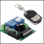
I'd like to use one of the many 12v universal remote relay switches available. The specs give an output current (less than 3 amps) and a max load current (less than 10 amps). What is the difference between these two? The relays on the board say 20a each.
Receiver:
1.working voltage :DC12V
2.quiescent condition :less than 6mA
3.working temperature :-40'c+80'c
4.receiver sensitivity : more than -105dBm
5.working frequency :315MHz
here is in set .we have made it work together ,so you don't have to care about what frequency are they .
6.output voltage:DC and AC is optional
7.output current : less than 3A
8.max load current:10A
9. Dimensions: 72mm*52mm*26mm
https://www.ebay.com/itm/12V-4CH-Channel-Wireless-Remote-Control-Radio-Relay-Switch-T ransceiver-Receiver/122036934849?_trkparms=aid%3D111001%26algo%3DREC.SEED%26ao%3D1%26 asc%3D20160727114228%26meid%3D65e79ccb5a0049b696ba053df6271241%26pid%3D100290%26rk%3D 1%26rkt%3D4%26mehot%3Dpp%26sd%3D122036934849%26itm%3D122036934849&_trksid=p2060778.c1 00290.m3507
|
|
sloweather
Member
|
# Posted: 8 Apr 2018 06:13pm - Edited by: sloweather
Reply
SEE MY NEXT POST. It has a rev counter, not limit switches.
Use a multimeter and check the 5 wires against each other with the actuator at each end and in the middle. They are likely the limit switches, but no rated for full motor current.
You have to remember that these are made for varying installations.
If the limit switches were in circuit with the motor leads, once one was opened, you'd never be able to run the motor again.
Or, there may be a rev counter in the actuator that the board reads to know the gate position. You could use the resistance setting on the meter and also check the 5 as its running to see if theres a pulse from a rev counter.
|
|
sloweather
Member
|
# Posted: 8 Apr 2018 06:22pm
Reply
Here's what one looks like inside:

From http://www.gateopenersunlimited.com/Mighty-Mule-MM502-FM502-Gate-Opener-Replacement-P arts.html
It does have a rev counter (part 5) and part 28 could be the chopper wheel that drives it.
|
|
toyota_mdt_tech
Member
|
# Posted: 8 Apr 2018 08:27pm
Reply
Thick red and black, be your power source. I suspect its low voltage DC, I suspect the motor is a permanent magnet type, so just reversing polarity makes it run opposite direction. I suspect other wires are probably limit switches to stop it when it hits the end of where you set the switches and I imagine polarity is swapped inside the control box.
I see a rotor, may use a more sophisticated hall effect set up too.
|
|
paulz
Member
|
# Posted: 1 May 2018 11:57am
Reply
Got my gate openers working! Well one gate opener, I converted my double gate into one long one, works better. I bought a cheapo 10 buck 12v dual remote relay deal like this, wired it switch polarity, working great! Took the limit and pressure switches out of the gate ram, I just hold the button down till it opens or closes, simple two wire hookup.
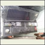
Anyway, I have a deep cycle marine battery powering it. I found this old HF dashboard solar panel on the shelf, took it out in the sun, put out 22vdc. I get about 3-4 hours of sunlight down at the gate. Can I just clamp this on the battery, or will it overcharge or drain it? Do I need some kind of control, a diode? It has nothing, just battery clips. The gate gets used about 6 times a week.
0430180919.jpg
| 
Capture.JPG
|  |  |
|
|
DaveBell
Moderator
|
# Posted: 1 May 2018 09:09pm
Reply
Did you lubricate the opener?
|
|
paulz
Member
|
# Posted: 2 May 2018 11:02am
Reply
No I haven't, good idea. Thanks!
|
|
paulz
Member
|
# Posted: 22 Sep 2018 07:51pm
Reply
My gate has been working great using the universal remote gizmo shown above. What a relief not having to get out of the truck twice every time. I have it wired up as shown below. There is only one problem: sometimes I forget the remote, like this morning when I rode my motorcycle down to the gate and had to get off and take the stupid ram off to open the gate and go have breakfast.
So, I got a two way toggle switch to hard wire at the gate so I can open it that way. I wired it on a separate circuit: battery to switch to gate motor. It works fine, except when I hook up both it and the remote gizmo. I think when I flip the toggle switch it back feeds current to the remote relays instead of the gate motor. Are diodes what I need?
|
|
ICC
Member
|
# Posted: 23 Sep 2018 09:45am
Reply
The wiring to those relay switches is confusing to me. You don't have any connections to the 12 volt input twin connection block?
|
|
paulz
Member
|
# Posted: 23 Sep 2018 10:29am - Edited by: paulz
Reply
No, just how it shows. Couldn't figure out how to switch polarity with just the two relays, an electrician told me to wire it this way, works fine. I just hold the button down until the gate gets where I want it and release, no limit switches. The terminals are marked Normally Closed, Com and Normally Open, left to right.
Found a couple of 6A2 diodes, going to try sticking them in there somewhere..
|
|
AmyYoung
Member
|
# Posted: 26 Jun 2020 07:11am
Reply
I have bought the switch to my garage door too. But did not manage to put it in functionality as my tehcnical knowledges are very low.
It was staing in my garage for about 2 months. Then one of my neighbours recomended me the advantagegd.com.
I have called them and fixed the appointment on the next day. Guys came and istalled it with no problem. It was very fast and the price is affordable.
|
|
|

